Project Andromeda
design and development blog

New Autopilot

     Posted on Mon ,15/08/2011 by Nima
  • Facebook
  • Twitter
  • Digg
  • del.icio.us

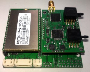
After our recent success with the previous incarnation of the Autopilot, it was time indeed for a new iteration of the Autopilot hardware. I was a bit weary of the size and cost of the previous version due to the use of the AT91SAM9XE chip which comes in a giant TQFP256 package and also the ADIS16400 sensor which goes for about $700 on Digikey. After a somewhat lengthy research period, I settled on the STM32-F2 line from ST Micro. Although since they run at only 120Mhz (as opposed to 200Mhz for the AT91SAM9XE) I would need 2, but since they come in a much smaller package, this was not a problem. Here is the finished product:

Newest iteration of the Perseus Autopilot.

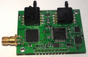
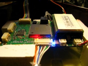
The DNT900 persists in this design as before, but the right hand side houses the IMU on top of the Autopilot MCU underneath. They use the same STM32-F2 chip but wired entirely differently. On the IMU I opted to use an LSM303 and an IMU-300, the combination which provides 3 accelerometer, 3 gyroscopes and 3 magnetometers. This is coupled with a differential and static pressure sensor pair read out at 20bits of ADC resultion and a Venus GPS receiver. I’m still not sure about the Venus but I’m willing to experiment with it, if not in the next iteration of the IMU I’ll revert back to the uBlox.

Close look of the IMU daughter board.

On top of this, I opted to use the JTAG connectors from Tag Connect to facilitate the connection to the debugger. These connectors are spring loaded and take up a very small footprint on the board, as seen above. I highly recommend them for their product and excellent customer service.

With the boards done, I’ve started the task of porting the code to the new platform, which isn’t without its own nuances, but provides a good opportunity to sort out some bad practices. Stay tuned as there will be some more updates soon.

Autonomous Flight Tests

     Posted on Tue ,02/08/2011 by Nima
  • Facebook
  • Twitter
  • Digg
  • del.icio.us

At long last the new Autopilot had a chance to prove its guts. Over the weekend we performed our first completely autonomous flights with the new Autopilot and our glider test aircraft. This was the culmination of a number of years of work on the Autopilot and AHRS as well as getting our processes to a point where we can perform successful take-offs, landings and switch-overs to Auto in flight.

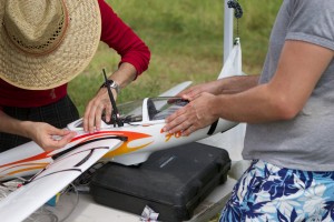
Closing up the canopy , just before launch.

Once the plane was at a safe altitude, Damien flicked up the 6th channel on the RC transmitter. The Autopilot received this command and took control of the plane. At the beginning, we tried partial autopilot functions such as roll hold and pitch hold, with Damien controlling the other surfaces. Once we had confidence was raised, we tried waypoint navigation. Although there were some glitches in the vector navigation (near the point with two close waypoints), the plane does a fairly well job of keeping to the waypoints even in the face of significant north easterly winds. In this video, the real-time ground station telemetry is shown. At the beginning, the plane is under Damien’s command. Once he switches over, it’s possible to see the autopilot status change on the left and the HSI shows the autopilot as it commands the plane.

In the small box in the bottom left corner of the map, any error flags received from the plane are shown. During the flight we had some very steep corners where the centripetal correction was not enough to give proper readings on the accelerometers. The AHRS is programmed to sense these anomalies and avoid correcting with accelerometers as long as they persist, and these errors are shown to the user in real-time. Here is the same flight but from the view of a GoPro mounted on the plane. Unfortunately it’s mounted a bit skewed.

On the south western leg the wind is a bit too strong and the plane drifts out of the path even while attempting to push back in. With the activation of the wind predictor Kalman Filter, the Autopilot should be able to correct for this and maintain a much closer approach to the path.

Net Arrestor System

     Posted on Sat ,07/05/2011 by Nima
  • Facebook
  • Twitter
  • Digg
  • del.icio.us

The design of the Andromeda catapult launch system was undertaken in order to provide a short tale-off ability for situations where a runway is not easily accessible. Needless to say, a short take-off is not useful without a corresponding short landing. We designed and implemented a large net based landing system for the Andromeda platform. The net interfaces to a small hook on the nose of the aircraft which in a future iteration should be retractable. After the initial design and static testing, we decided to test the net with the composite Andromeda body:

Once again our fearless pilot Damien managed to pull off a very impressive landing, putting the nose almost at the centre of the net. The aim of the full vehicle is to be able to land into the net autonomously using a combination of vision and inertial based navigation.

New Composite Airframe

     Posted on Wed ,02/03/2011 by Nima
  • Facebook
  • Twitter
  • Digg
  • del.icio.us

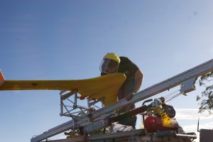
Matt fixing up the petrol powered Andromeda on the catapult.

We’ve been very busy getting the new composite airframe ready. At the moment, our construction method is a simple foam laminate. The body has already been modelled in CAD. We then feed this model in a two step process to the CNC machine. Once on the top and then on the bottom. This yields a perfectly formed foam core which we can laminate with fibreglass. The result is an extremely rigid but lightweight body. The downside is that since we are not using a female mold as before, the surface finish is nowhere near as nice after fireglassing. However with a little bit of sanding we can get an acceptable finish in a fraction of the time it took us before.

We’ve also upgraded our pneumatic launcher. Previously the arrestor system consisted of spring loaded rams at the end of the rail which impacted on the carriage to slow it down. This turned out to be a bit too much on the components of the carriage as the ball bearings and joints started to shift after repeated launches. We then settled on a system that used the ram itself to slow the carriage down and it worked much better:

With the launcher and body set to go, we started conducting a number of tests to make sure that the launcher was properly performing the steps needed to launch the aircraft. This included holding the aircraft stationary during the power up sequence to allow the motor to develop sufficient power, and releasing the aircraft at a predetermined position on the rail. After checking the CG of the aircraft we attempted a number of flights with our on-board GoPro video camera and managed to capture some spectacular views:

In the first two videos it can be seen that the plane shifts a small amount in the carriage grips. This was due to an earlier design whereby two sets of soft grippers were CNC cut to adhere to the shape of the wing. We have since replaced this system with an alternative using adjustable screws with rubber tips to hold the aircraft. Needless to say, both flights were done in Manual mode with Damien, our fearless pilot in command.


System Integration

     Posted on Wed ,29/09/2010 by Nima
  • Facebook
  • Twitter
  • Digg
  • del.icio.us

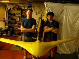
The past few weeks have been very busy for all of us. Our first Andromeda airframe is finally complete and ready for testing. Matt and Damien have been busy attaching the separate sections of the plane, sanding and painting the final shell. Due to the monocoque design, all the stresses of flight are carried along the skin. The seam where the top and bottom sides of the shell join also carries shear stress and therefore is important to the structural integrity of the aircraft. The following is Matt and Damien behind the finished shell:

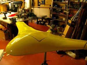
And a closeup of the body and hatch:

There is a slight droop to the wings in these pictures. This is due to the way the wings and the body join. Our intention is to continue the stress along the shell through the wing-body join. Our solution involves a smaller section at the end of the wings which inserts into the body. This insert is then squeezed to the body using a double row of screws. The result is that the skin friction between the two shell sections is the main medium through which the bending stress is transferred, as opposed to shear in the bolt. This is known as a bolted joint.

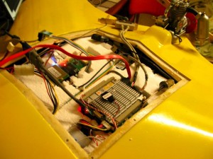
On the other hand, I’ve been busy integrating the autopilot and visionics into the body. The current state is shown in the following picture:

The foam insert visible in the picture above was machined by using the 3D models of the plane and the electronic modules. The far module is the Perseus Autopilot. The module closest to the camera is a PCI/104 stack consisting of a 1.4Ghz Intel Atom processor, MPEG-4 frame grabber and mini-PCI wireless card module. While the Perseus autopilot is responsible for guiding and navigating the plane, the PCI/104 stack is responsible for compressing the analog video from the camera and sending it to the ground station via a wireless link. Further image processing can also be done on this module as both compressed and uncompressed stream of images are available from the framegrabber.

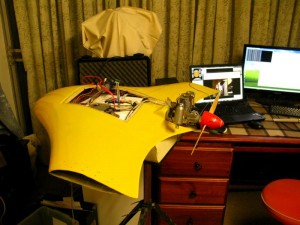
The picture on the right shows the video from the camera being transmitted from the PCI/104 stack (monitor on the right) and being decompressed on the monitor on the left (ground station). The end-to-end latency is around 200ms.

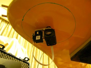
The following picture shows the pan/tilt/zoom camera system attached to the underside of the shell. The pan, tilt and zoom are controlled by the PCI/104 stack computer. This allows the computer to track features on the image by moving the camera. I will detail this in a later post.

We haven’t installed the perspex dome that protects the camera yet, but the outline can be seen in the picture. The dynamixel that does the panning is actually inside the aircraft.

And last but not least, here are some videos of powered and unpowered tests of the shell before it was painted by Damien. In these videos, the plane is only controlled by standard RC equipment. The launcher and catcher mechanisms are also put to the test:

As you can see, the center of weight of the aircraft is not yet optimal as some instability can be seen in the second video. We are in the process of testing our systems with our Faux Andromeda test plane ‘Fandromeda’. I will post more on this soon. Stay tuned!

The Perseus Attitude and Heading Reference System – Part 1

     Posted on Thu ,05/08/2010 by Nima
  • Facebook
  • Twitter
  • Digg
  • del.icio.us

One of the biggest challenges of controlling an aircraft, is obtaining the situational awareness required to correct the errors that would put you off-course or in harms way. For level and safe flight, an aircraft needs to maintain a certain airspeed while staying level. It must also remain at a certain altitude and not climb/descend. A human pilot would use a combination of the instruments available to him, and his own internal sensors, to observe the position, velocity and altitude, or collectively, the state of the aircraft. A UAV must also do the same in order to be able to fly with stability and navigate a given course.

One of the main instruments in the pilot’s arsenal is the artificial horizon. This instrument attempts to stay fixed to the horizon as the aircraft banks and tilts around it, giving the pilot an indication of where the aircraft is pointing relative to the “flat” ground. In their original mechanical forms, these instruments were cumbersome and heavy, requiring a vacuum system to operate properly. Small UAVs would be unable to utilise these sensors in their mechanical incarnations. however in the past decade a new variant of inertial sensor has emerged. These Microelectromechanical sensors , or MEMS for short, provide information about the rate of rotation and acceleration of a body in space. Their tiny size and negligible weight renders them perfect for use in small UAVs. Tim Trueman of DIY Drones has an excellent article which covers some history on these inertial sesnsors.

The Perseus Autopilot, which is responsible for controlling the Andromeda UAV uses the Perseus AHRS (Attitude and Heading Reference System) to determine the state of the vehicle. This allows it to correct the pitch, roll, heading and position of the aircraft.

At its heart, the Perseus AHRS consists of a block of 9 sensors and a statistical filter known as a Kalman Filter. The 9 sensors measure gravity, angular rotation and magnetic field strength in 3 axes. The magnetic sensors (referred to as magnetometers) and acceleration sensors (accelerometers), provide the measurement of two vectors in the frame of reference of the aircraft. The acceleration vector, and the magnetic field vector are known quantities in the earth frame of reference. We know that gravity points down and that the magnetic field points north (roughly). The measurement of these two vectors in the aircraft frame of reference, having known their actual values in the earth frame of reference can give us a clear idea of how much the aircraft has rotated to result in the measured values. The calculation of this rotation (or attitude) is known as Wahba’s problem.

Below is a demonstration of the AHRS system using a simple 3D visualisation application. The application reads the attitude information through the serial port and displays them as a 3D rotation of the object.

The source code for the 3D visualisation application is available here.

As you can see, the representation of attitude in the visualization, is obtained by the monitoring and filtering of the 9 sets of sensors that are all integrated into the “cube”. So how does the Kalman filter solve Wahba’s problem and make sense of the 9 separate bits of information? To explain this, imagine that you are watching a large jumbo jet fly over your house. It’s a particularly cloudy day so the airplane promptly disappears above a cloud directly above you. Knowing the previous course and velocity of the plane, you continue to track it, without seeing it – anticipating its appearance at the other side of the cloud. Eventually, the plane appears and more often than not you have been waiting for it at almost the correct spot. What you have done is observed a process, namely the movement of the plane and also made a prediction of where the process would lead to next.

Now let’s assume that the plane enters a banked turn. As it appears out of the cloud, you realize your mistake and start tracking it again as it enters the next cloud. This time, you are aware of the fact that the plane is turning and therefore anticipate the planes appearance at a corrected location at the other side of the cloud.

This observe->predict->correct cycle is the fundamental method through which the Kalman filter makes sense of the noisy sensor data. The Filter is designed around a model – a mathematical equation that links the 9 sensors to the attitude of the craft. It is also aware of certain parameters such as the relative accuracy of the process to the measurement. In our previous example, this would translate to your relative confidence in your ability to predict the path of the plane to your ability to measure its position. In this case, your ability to measure it would exceed your ability to predict it. Based on this relative accuracy, the model which we have defined and also the ongoing observation of the process, the Kalman filter can then use both the prediction and the measurement to make a guess at the state of the model which links all variables together. This simplified explanation forgoes a lot of the mathematics that makes the Kalman filter so useful, however the fundamental concepts still apply.

We can now go back to our initial problem, which was determining the state of the UAV. Using the aforementioned AHRS, we have obtained the attitude of the aircraft but have no information on the position, altitude and airspeed all of which are very important. The next part of this article will focus on how the Perseus Autopilot combines the attitude information from the AHRS with the GPS position, airspeed and altitude data to obtain a stable and accurate state for the UAV.

Stay tuned!

Airframe Developments

     Posted on Wed ,30/06/2010 by Nima
  • Facebook
  • Twitter
  • Digg
  • del.icio.us

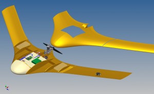
Matt has been very busy drawing up all the components of Andromeda in CAD. We decided to produce a very detailed CAD model to iron out any potential issues early on. The basic shape of the plane has changed slightly from the conceptual models on the website and this has been due to aerodynamic modifications, instrumentation placement and engine interface. The following is a picture of one of the recent assemblies which includes the airframe, electronics for control and video telemetry, engine and fuel systems and actuators:

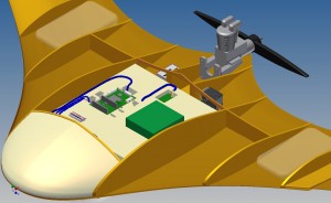
As you can see in the illustration, our design involves a 3 piece airframe. The center piece contains the fuel, propulsion, electronics and power systems while the wings attach to the main section via bolted-on inserts. There are also plans to include winglets at the ends of the wing to facilitate yaw stability. The central hatch in the top section is to allow access to the electronics since the top and bottom sections -whilst manufactured separately – will be joined permanently during assembly. Here you can see a closeup of the central section and electronics:

The green board on the left is the Perseus autopilot while the green box on the right is the PCI/104+ stack which handles the compression of the onboard video and the video telemetry downlink. Matt has also included the preliminary wiring between the autopilot and actuators. This will be built upon to include the complete wiring harness diagram and fuel system piping to ease the conceptual design and assembly of the aircraft. The front of the aircraft which is pictured above will be composed of a large sacrificial foam section to protect the electronics in case of a crash and it will also house the batteries.

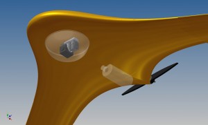
The underside of the aircraft will include a gimbaled camera system as well as the bottle which will be dropped as part of the requirements of the Outback UAV Challenge.

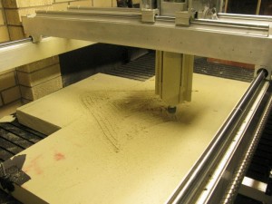
Damien and Matt then created CNC code to create molds from these drawings. Here, our CNC machine which we have nicknamed Hephaestus (try pronouncing that!) can be seen machining the top half mold out of extruded polystyrene foam. Unfortunately the process is very messy and requires extensive cleaning due to the mass amounts of pulverised foam.

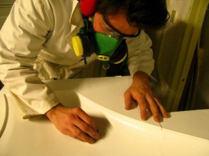
This pollution necessitates quite a bit of PPE, and with everything running at the same time, we have to look like this when working in the CNC room.

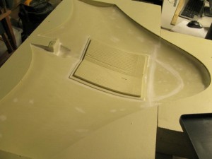
In the previous photo you can see Matt working on finishing the mold which requires sanding the numerous layers of primer that we put onto the surface. After the machining process, you can see the top section mold, fresh out of the CNC and with minor putty work to fill in some gaps in the joining of the foam pieces below:

The center square section is for the hatch that will eventually allow us to access the electronics and equipment inside the fuselage. The plan is to use the raised edges to create a “step” over which we can place and secure the hatch. The small section at the back is also the engine mount which interfaces directly to our engine system. Currently we have also machined out the bottom side mold and Matt is the process of treating the surface and preparing for the composite layup – a process which takes a day or two. Once we pull the body out, I’ll have some photos of the sections and their assembly.

I’ve also received all the components of the camera assembly, all of which are very cool. I’ll post our progress with the gimbal, software and telemetry of the camera system very soon. Stay tuned!

Interrupt Based Programming for Microcontrollers

     Posted on Wed ,30/06/2010 by Nima
  • Facebook
  • Twitter
  • Digg
  • del.icio.us

I’ve recently been doing a lot of interrupt-based software development on the Perseus Autopilot. There’s quite a few things that need to happen Asynchronously on the Autopilot including sensor interfaces, control loops and communication/actuation loops. This can result in many interrupts that can sometimes even trigger at the same time. So how does one deal with all of this in an application? It might be worthwhile to first get into the details of interrupts, and then I will list a few pointers that could help you in your projects, if you are writing heavily interrupt-base code.

Normally, the code you write in C++ or C and most other languages that would run on a microcontroller (with the exception of assembly), will allow you to create, modify and work with variables. These language will also allow you to call functions, and in case of object oriented languages such as C++, allow you to create objects or classes. It is therefore important to get a good grasp of how these variables and objects are represented in the memory that is available to you (usually some form of RAM). The two sections of memory that we are interested in are the stack and the heap. This article is an good place to get some information about these memories. What is important to us, is what happens to these memories when an interrupt occurs. If an interrupt occurs during a function execution, the processor will stop what it was doing in that function, and depending on the type of processor will usually divert to an interrupt vector which will then call the ISR or interrupt service routine. Once the ISR has finished, the processor will return to where it left off in the execution. Note that the state of the processor before it left the execution must be saved, and restored once the ISR is completed. This will ensure any pending operations will continue correctly one execution resumes.

Variables that are used in the ISR will be allocated on a separate stack. This stack needs to be allocated in memory that cannot be used by the normal thread of execution in most states. The state of the processor before the interrupt is also pushed onto this stack. Since we are operating in an environment without an OS, everything runs in the same memory space. It is therefore very important to allocate enough heap and stack memory for your application as exceeding these memories will cause undesirable and unpredictable problems.

Things can go wrong in several cases with ISR programming, and these errors are often extremely hard to debug. One scenario is if a variable is accessed from within an ISR and from within normally executed code at the same time. In this case, if the variable is not accessed atomically, the processor can be interrupted half-way through a read/write operation on the variable. If the ISR then modifies the variable, when execution returns, the value of the variable that will be used can become invalid. This can happen if global/static variables are modified from within and outside of an ISR simultaneously.

With that in mind, these are a couple of tips to help with developing interrupt-based systems without the use of an operating system:

- Plan Ahead

Draw your functions or write them in pseudo-code. Find out exactly what you need in the ISR and do everything else to the normal execution thread. It might also be worthwhile to list all the functions that the application must do, and deciding which ones are time-critical and therefore need handling via ISR. Everything else can be done via polling in the main thread. Figure out when your interrupts are likely to happen, and what variables they access/modify.

- Nested Interrupts are Extremely Nasty

It is generally a good idea to disable all interrupts once an ISR is entered. Even though it might seem logical that ISRs should be “interruptable”, it will make writing secure and reliable code extremely difficult. The simultaneous execution of multiple interrupts can rapidly fill the stack allocated to the interrupts. Once the ISR has finished, interrupts can be enabled and in most processors, the corresponding ISR will fire if an interrupt happened.

- Keep It Short. Very Short

Lengthy ISRs can create problems as they will halt the execution of your main thread at potentially unpredictable and lengthy intervals. If nested interrupts are disabled (which they should be), lengthy ISRs can also reduce the speed at which your processor can respond to interrupts. Start the ISR, get what you need and get out. Do all the processing in the main thread unless you absolutely must do otherwise.

- Don’t Call Functions

Unless you really have to. Calling functions in an ISR will lead to the arguments and variables being pushed into the ISR stack which will increase its size. If functions that are called from within an ISRs are also called from the mean thread, it can lead to issues if the function is not designed as a re-entrant function. This means that the variables that the function declares, should be locally instantiated and specific to the execution context. Here is a good article on writing re-entrant functions.

- Use Volatile and Atomic Variables

If you are accessing variables both from within and outside and ISR, declaring variables with the volatile keyword will make sure that the compiler does not use any optimisations in the code. This means that the code will run just as you wrote it, which is not always the case as the compiler makes many optimisations to increase performance. Volatile, in-built variables are generally atomic in their access (except for arrays) but it pays to always check this with your compiler. If you are accessing arrays or objects, you can make them atomic by disabling interrupts when you access them from the main thread. This will make sure that they cannot be modified by the ISR whilst your are working with them in the main thread. In this critical section you can them copy the data from the volatile variables to local ones which the ISR doesn’t access, and re-enable the interrupts.

If you can think of any more, drop me a line/comment so I can update this.

The Perseus Autopilot

     Posted on Wed ,30/06/2010 by Nima
  • Facebook
  • Twitter
  • Digg
  • del.icio.us

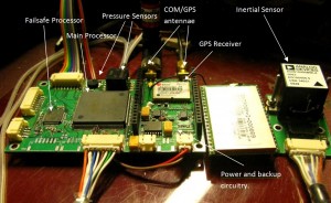
In keeping with the tradition of our Greek Mythology inspired naming, I give you the Perseus Autopilot which will control the Andromeda UAV (Click on the picture for a bigger view). I have spent the better part of the past 6 months working on this Autopilot. It builds on a lot of experience gained in making our previous autopilots. The major step forward in this version has been the integration of a Extended Kalman filter based AHRS as well as a separate failsafe controller and an improved communication radio.

The following board is the first prototype version and as such there are some minor hardware fixes require that will be implemented in the next (release) version.

Hardware

At the heart of the autopilot, you can see the (rather large) Atmel ARM9 flash microcontroller running at 200MIPS, similar to what you would find in some mobile phones. The smaller microcontroller to the left of it is an ARM7 running at about 50MIPS. The ARM9 is responsible for running the main Kalman filter and control loops while the ARM7 is a failsafe processor which controls all the Dynamixel actuators, as well as decoding the PWM signals that it receives from the ground based controller.

On the right you can see that large DNT900 radio. Once removed, the underneath looks like this:

The circuitry closest to the camera, is the switch-mode power supply(s) and the backup battery switch. This allows the aircraft to use an axillary power supply if the main one falls below a specific voltage. This also allows us to use an onboard generator and battery simultaneously (in the future). Behind it, you can see the excellent Ublox-5 series GPS receiver which seems to acheive 3D lock even in the most unlikely and enclosed scenarios. The GPS and command antennas can be seen at the far end of the board.

Printed Circuit Board

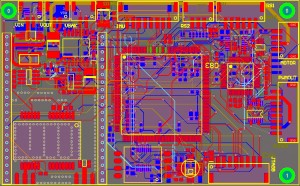
Due to the relative complexity of the board, this was also the first time I used a 4-layer board. The following is a snapshot of the PCB design with the ground layers removed:

The PCB is larger than most autopilots in the DIY community but unfortunately due to the large size of the Microcontroller and assorted sensors, I couldn’t shrink it down too much more. The space is not too much of an issue for us either, as there is plenty of room available in the aircraft.

Sensors

The Perseus AHRS (Attitude and heading reference system) is based on the ADIS16400 sensor by Analog Devices. This “cube” can be seen on the right side of the picture above with its orientation printed on the side. This sensor incorporates 3 axes of gyroscopes, accelerometers and magnetometers in a tiny package with all the A/D and filtering circuitry. This data is then used in the Extended Kalman filter that gives the Autopilot its pitch, heading and roll.

The Perseus also incorporates an SCP1000 digital barometer and temperature sensor as well as the differential pressure sensor seen above for measuring the airspeed. There are also multiple RS-232 and RS-485 sensor for integration with the onboard computers and actuators.

Software

The software has been by far the most challenging and time consuming aspect of it. I personally use the Crossworks package which I would recommend if you are doing serious microcontroller work over JTAG. The most difficult task in the software has been the asynchronous management of all the tasks that the Autopilot must do. These are:

  • Parsing, processing and send packets of the Ground Control communications radio. This includes error checking, handling, line checking and execution.
  • Communications with the failsafe controller
  • Communication and periodical acquisition of data from all sensors
  • Periodical updating of the Exteneded Kalman filter.
  • Periodical updating of the control loops.
  • Safety/emergency monitoring and management including power monitoring and communication monitoring

All of these functions must happen simultaneously with some interrupted whilst others proceed. Without an operating system to mange resources and threads, this situation quickly devolves into a complicated scenario. Keeping the processor at its peak, efficiently and reliably has been the largest challenge by far – exceeding the challenges of implementing the math-intensive Kalmnan filter or control loops.

Simulation

I’ve also been busy with extensive Hardware-In-The-Loop (HIL) simulation to work out existing reliability problems before flight testing the new autopilot. These HIL simulations have also been vital to the development of the Hermes ground station which I will introduce in a future article.

I apologise for the lack of updates, and as a result of this, there is a back-log of cool things we’ve been doing that I’m going to post within the coming days. As always, Stay Tuned!

CNC, Airframe and Antenna Update

     Posted on Sun ,06/06/2010 by Nima
  • Facebook
  • Twitter
  • Digg
  • del.icio.us

I’ve been a bit too busy lately and unfortunately haven’t had the chance to update the blog but it’s something that has been long overdue. There’s been a lot of progress on all fronts and I’m going to outline some of the stuff we’ve been doing in regards to creating the airframe and also the antenna gimbal.

Matt has finished the design of the aircraft in CAD and he’s been using the CNC machine to cut out the female molds that we’ll use for creating the composite surface. The aircraft is split into three sections which form the complete flying wing: the center section and two wings. At the moment he is fabricating the wing sections. I recorded a short time lapse video of the CNC operations:

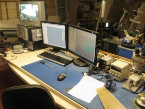
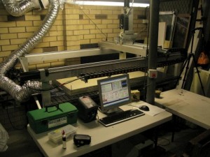
You can probably spot Matt vacuuming the work area every now and then. This is just so we can check that the surface finish is adequate. Usually we can just leave it but the mess of pulverized foam that is left behind is a bit daunting. We’ve definitely expanded our arsenal of PPE. You can also see that we’ve added cable drag chains to the CNC which have greatly reduced the mess around the machine. We’ve also enabled spindle speed control through Mach3 and a remote viewing station which allows us to continue working in the main workshop while the CNC cuts away safely in the other room (and quietly). Here’s a shot of what the CAD and CNC station looks like:

The TV on the left is hooked up to a CCTV camera which observes the CNC work area. The big red button in front of the TV is also an emergency stop button in case something goes wrong. Here’s what the CNC machine looks like now:

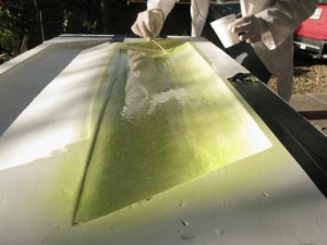
So far we’ve successfully cut aluminium and foam with it and it hasn’t given us too much trouble. Once the molds were cut, we finished the surface with a couple of coats of primer and paint and then started the standard layup procedure. Here you can see Matt prepping the mold for the layout:

As I’m writing this, the two sides of this mold are curing under a vacuum. We should have a complete wing ready to go in the next couple of days. I will definitely post more shots of the working wing when it’s assembled and painted.

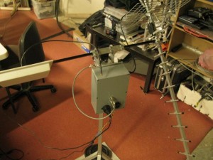
Another component that we finished a while ago and I’ve had a chance to post about is the ground station and antenna assembly pictured below:


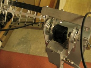
This unit hosts all the communication electronics and wireless antennae used to communicate to the Andromeda UAV. The Yagi antenna is tuned to 900Mhz and will be used to communicate on the Australian 900Mhz ISM for commanding the Autopilot. The patch antenna on the left operates at 5.8Ghz and is used on a digital wireless network for the relaying of video. All the electronics required for this to operate are contained in the grey box at the center of the picture. An ethernet and USB jack connect the video and command modules to the PC running the ground station software respectively. Below is a closeup of the pan and tilt mechanism:

There are 3 ball bearings in total which ensure that the only loads transferred to the Dynamixel servos are torque. The pan mechanism is located in the box under the top servo and attaches to the base of the mechanism. A lot of custom aluminium bits were made using the CNC machine for this gimbal. The design was done by Damien with some input by myself and we all participated in one way or another in constructing it since it was the first time we were cutting aluminium with the CNC.

I took a short video of the dynamixels moving the gimbal. In the video I am operating the servos through the ground station software on the laptop, which talks via USB to the ground station module on the gimbal. Note that I’ve set the speed and acceleration settings on the dynamixels and the result is a very smooth ramp up/down as the gimbal moves around:

There’s also a lot going on with the IMU and the autopilot, and we also have a new sponsor who generously supported us in obtaining an excellent camera for the plane. I will write this in the next update which will hopefully be tomorrow. Stay tuned!