Project Andromeda
design and development blog

Ground Station Electronics Box

     Posted on Tue ,20/04/2010 by Nima
  • Facebook
  • Twitter
  • Digg
  • del.icio.us

We’ve been making steady progress on all fronts as of late. Matt has been working on the ground station electronics box, which will house the ground station controller as well as the router housing the wireless cards. The difficulty of the setup is that the box must be waterproof as it will be exposed to the elements. A very solid box was chosen alongside IP68 connectors to facilitate water resistance.

The inside can be seen below:

The insert was CNC machined but due to some inexperience and unforseen issues we had to do some manual cutting and incision-making afterwards. The antenna on the ground station is temporary and is used for development purposes. The Autopilot sends the inertial and sensory data through the wireless link to the ground station which then relays the information to my laptop via USB:

The USB and ethernet connectors are for command and video data respectively. The other two connectors allow the ground station controller to command the dynamixel servos responsible for rotating the antennas. A connector also links the grond station controller to the catapult allowing it to launch the catapult remotely and also to measure the launch speed via a microswitch.

Next up is the construction of the antenna gymbal. Matt and Damien are gearing up to begin construction. They are also about to start making a small version of the final airframe for aerodynamic testing. I have also been making good progress on the Kalman filtering for the AHRS. I’ll post results as soon as they’re in. Once the AHRS is finished, I will easily be able to port the navigation code from last year’s autopilot and begin doing full autonomous tests. As always, stay tuned as more news will be coming up soon!

Podcast with DIYDrones

     Posted on Tue ,20/04/2010 by Nima
  • Facebook
  • Twitter
  • Digg
  • del.icio.us

I recently did a podcast with Chris Anderson and Tim Trueman of DIYDrones who were kind enough to invite me to discuss Project Andromeda. The podcast covers some background information about the project, its members, goals and scope. Check it out here.

Catapult System and New Sponsors

     Posted on Mon ,12/04/2010 by Nima
  • Facebook
  • Twitter
  • Digg
  • del.icio.us

The past few weeks have been quite busy for us. We have made arrangements with Tribotix and they have generously agreed to sponsor us by providing us with Dynamixel servos at highly discounted rates. We will be using these servos as the main actuators for both airborne and ground-based purposes. Discount Hobby Supplies have also generously agreed to sponsor us by providing the petrol 4-stroke engines we will use for the Project Andromeda vehicle at discounted rates.

We have also been busy developing our new launch system. Last year due to time constraints, we had been content with a wooden launcher using a bungee chord for potential energy. This year we decided to use a pneumatic cylinder for potential energy. Damien had been busy drafting up the first version of the launcher. A lot of small problems were sorted out in CAD and once he had finalised the drawings we could begin the construction. Our wooden launcher used a dual rail system to simplify the problem of clearing the propeller. This year we decided on a single rail system which meant that we also had to design a “truck” to carry the aircraft so the propeller doesn’t strike the rail. The result is as follows:

The first test shows the launcher with a 5kg plank and the second one is with a simple RC aircraft. The tests were conducted with about 50% of our working pressure as we are still unsure about the arrestor mechanism and we didn’t want to damage the truck. The launcher is actually attached to the Andromeda Van and apart from a few curious onlookers, we can generally move it about quite easily and safely. Also for safety, we decided that all operation of the catapult should be done remotely so Matt created a control panel through which we can control the compressor, view the launch pressure and finally launch the plane (the button with the red cover as shown below):

The launcher also includes sensors to detect when the truck is in the locked position and also a speed sensor which detects the truck’s movement and will be used to determine the launch speed. All the signals pass through the control box above and go to the Ground Station Controller circuit which will be located up on the antenna mast.

One of our design goals was to allow the plane to ramp up to full throttle before launch and this can be observed above as the RC plane is at full throttle before the launch. The truck then releases the aircraft at a predetermined point on the rail and the aircraft is free to continue forward.

Once we upgrade the arrestor mechanism I’ll post some videos of launches with higher pressures and velocities. Stay tuned!

Communication Protocols

     Posted on Tue ,23/03/2010 by Nima
  • Facebook
  • Twitter
  • Digg
  • del.icio.us

With the introduction of the Ground Station, I have spent the past couple of days writing the framework that handles the communication between the Ground Station and Autopilot. The previous incarnation of the Ground Station was simply the ground radio connected via USB to the laptop. The code handling the communication would therefore run on the laptop. In the new version, this code now runs on an ARM7 microcontroller. The goal is to have the Ground Station in continuous communication with the Autopilot, updating variables at different rates and storing them locally. The Ground Station software running on the laptop would then simply read these updated values through USB from the ARM7.

With that in mind I set out my goals for the communication framework:

  • Object orientated approach using “Command” objects containing the commands and respective data.
  • Asynchronous queuing of “Command” object, allowing multiple threads to send commands at the same time.
  • Handling of data received from the radio, and associating the response to the correct command.
  • Operation using DMA (Direct Memory Access) and interrupts only, saving processor time

This framework will run on both the Autopilot and Ground Station using the RFM DNT900 radios mentioned in previous articles. The DNT900 radios are used in protocol mode which allows the setting of a destination MAC Address and also packet length. On the receiving side, protocol mode provides a distinct header which can be used to pick out the beginning of the packet.

The ARM7 architecture from Atmel has very extensive DMA coverage of all peripherals. The UARTs used to communicate with the radios have Rx and Tx double buffer DMA channels which allow uninterrupted reception or transmission of data without processor intervention. Interrupts are also provided when the buffers are empty (in case of Transmission) or full (In case of Reception).

The picture below shows what’s going on in a high level flowchart (click to enlarge):

To explain what’s going on, I’ll start at the Ground Station. The first thing to note is that commands can be Queued both from the USB interface and also periodically. This allows the Ground Station software to issue commands to the DNT900 via the USB interface (such as read a radio register). Periodical commands will be used for retrieving telemetry from the aircraft or updating control surface positions when required. The command queue will make sure that no collisions take place as new commands are added.

The Tx Empty interrupt is employed to signal when the UART transmitter has finished doing whatever it was doing and is ready to send. The command is then sent through the radio to the Autopilot. On the receiving side, as commands are received, their DNT900 CommandIDs are matched to the commands in the queue to determine their original command. The data is then copied to that particular command object and a status flag is set for that command (If the command was a data Rx/Tx command, a callback function is called).

The reception is achieved completely through the DMA and interrupts. The processor sets the DMA to generate an interrupt when a packet header is received. This packet header contains the length of the total packet. A second interrupt is then set to fire when the entire packet has been received. Therefore each packet is received via 2 Rx interrupts and with minimal processor overhead.

On the Autopilot side, the entire process is repeated with the exception that the Autopilot will only send commands in response to an original inquiry or command from the Ground Station. This “polling” system allows the Ground Station to talk to multiple Autopilots at once without collision. The interrupt and DMA driven system also frees up the processor and simplifies the act of sending a command. You simply create a “Command” object and populate it with data and push it into the FIFO. When a response is received for your command or if it times out, a status byte will be set accordingly on your command object. For periodic commands, a Callback function is called to facilitate the transfer of data from the command to the registers of the Ground Station or Autopilot.

To simplify the operation of the Ground Station, I have also implemented its “Configuration” in the form of registers with an address and category. These registers can then be read/written to from the USB interface to change the configuration of the Ground Station. This configuration includes things such as transmission power and time interval for periodic commands.

At the moment I’m still ironing out some bugs but it’s looking good to go for our flight this weekend. I’m hoping to have the ground station collect some data from the Autopilot while Damien manually flies the plane. Stay tuned!

Ground Station and New PCBs

     Posted on Tue ,09/03/2010 by Nima
  • Facebook
  • Twitter
  • Digg
  • del.icio.us

We got our first PCB panel under our sponsorship arrangement with the nice folks over at Advanced Circuits. The production quality and speed were as good as ever. You can see the autopilot section of the panel below:

Autopilot PCB

With the components also arriving, I begun soldering the Ground Station PCB. In this iteration of the Autopilot/Ground Station I decided to go with the DNT900 radio from RFM. Our previous boards used the AC4790 radio from Aerocom but our experiences were less than satisfactory. The DNT900 promises speeds of up to 500kbps and a transmission output power of 1W (albeit only until 200kbps). It can be used as a transparent serial cable replacement, however the true potential of the radio is in its protocol mode operation due to the overwhelming choice of features and tweaks. At least compared to the AC4790. The DNT900 can be seen as part of the ground station below:

DNT900 on the ground station

This PCB will eventually sit on our soon-to-be-constructed gimbaled antenna stand so I needed to keep it small. All the components roughly fit underneath the footprint of the DNT900, which is convenient. The u.fl connector on the DNT900 is way too sensitive for tampering so I broke it out to an SMA connector (visible above). The cable assembly comes standard from Digikey, very thin but surprisingly strong. The Ground Station with the DNT900 disconnected can be seen below:

Ground Station Interior

The Processor is a standard ARM7 from Atmel. Specifically the AT91SAM7256. All connectors are JST PH series. I really recommend these connectors for any space-limited circuits as they have excellent mechanical integrity as well as being easy to crimp/solder. Unfortunately I was only able to fit in 1 mounting hole. That will be an interesting challenge once it comes time to installation, but since this board will be under minimal vibration or acceleration, I doubt it will be too much of an issue.

Ground Station Underside

The underside of the PCB can be seen along with the expansion and motor control connectors. This PCB is designed to work with Dynamixel servos which operate on an RS485 bus. PWM outputs are included however as a necessary backup.

In previous incarnations of our Ground Station, the host computer would communicate directly with the ground based AC4790 through a USB to Serial converter. This was simple, however it was also susceptible to fail if the host computer were to crash (We’re talking about Windows, so I have to consider the chance). The advantage of the separate Ground Station is that it can maintain continuous communication with the UAV even if there is no computer connected.

Ground Station with Connections

As can be seen above, the JTAG programming port has been broken out onto a separate PCB through a JST connector. This is due to the fact that the standard connector is bulky and would consume too much space on the PCB. The same JTAG connector will also be used on the 2 microcontrollers aboard the autopilot.

For the USB communication, I decided against using an FTDI or other standard USB to Serial chip. I instead opted to implement a HID driver interface for the Ground Station. Examples for this are available from Atmel. In accordance with the new Ground Station design, I’m also overhauling the Software which runs on the host computer (well, more like a complete re-write). The progress is mostly behind the scenes at the moment but I have built some basic interfaces for tweaking the radio:

Ground Control Station Software Radio Options

The above UI is still very basic but most of the work has been implementing the functionality behind the scene which manages the USB connection. This ensures that commands that are given to the USB handler are sent one at a time with an appropriate timeout to protect against any drop outs. The resulting latency is very good (about 10ms) since the HID system supports Interrupts Endpoints (used for devices like Mouse and Keyboards) which are meant for low latency communication. This will allow more fluid manual control of the UAV via a ground based Joystick through the long range radio.

I’ve ordered some new solder tips and will hopefully finish soldering the autopilot in the coming week. I’ll also be posting some updates on our pneumatic launcher in construction. Stay tuned!

New Sponsor

     Posted on Thu ,04/02/2010 by Nima
  • Facebook
  • Twitter
  • Digg
  • del.icio.us

We are proud to announce that Advanced Circuits have generously agreed to sponsor Project Andromeda for the 2010 Australian Outback UAV Challenge. We have been a customer of Advanced Circuits for a long time and produce all our PCB circuits using their services. The new versions of the autopilot board will soon be sent off for production.

Visit the Advanced Circuits sponsor profile for more information.

CNC Machine Design and Construction Highlights

     Posted on Wed ,03/02/2010 by Nima
  • Facebook
  • Twitter
  • Digg
  • del.icio.us

Everyone should have a CNC machine. Or at least everyone building a UAV should try and get one. They are such useful tools and one can never know unless you have one at your disposal. To create the Project Andromeda aircraft, Damien and I embarked on building a relatively large CNC machine. Large enough to create our wing molds. We agreed on a 2mx1m overall dimension and began planning.

Damien took the helm by drafting up the initial layout of the machine. We visited a local aluminium distributor and Damien promptly drafted their entire catalog into AutoCAD. This step proved to be a lifesaver as we could never have put everything together without the simplicity of selecting stock within AutoCAD. By this stage all our components had arrived. The 2m long X axis ballscrew, the 3 4.5kg motors that would drive the ballscrews and the 5kg spindle. Damien’s initial design was maturing and by this stage all our measurements were in CAD.

It was around this time that my curiosity got the best of me and I managed to dislodge the ball bearings out of the Z axis ballnut/ballscrew assembly while tinkering with it. Little did I know that this would start a saga of misery that would only see closure by the perseverance of Damien in figuring out how to “reball” a ballnut: an apparently impossible task.

The Z axis proved to be the hardest section to design and build. The spindle was very heavy and we needed to keep things close in order to limit the moment arm imposed onto the ballscrew assembly. Damien came up with a very tight design that can be seen below:

The spindle is almost touching the Z axis ballscrew with only a couple of millimeters to spare. Another tight fit is the Y axis ballnut visible near the bottom of the spindle. Its circumference just clears the Z axis ballscrew leaving a tight fit that allows as much movement as possible for the gantry. The picture below shows the clearance at the front of the gantry, which is about 2mm. This allows the Y axis to be sized down as well, increasing the X axis working area.

After the painstaking task of assembling the Z-Y axes, we finally moved on to the X axis which proved to be almost as hard. The process of making sure the 2m long fully supported rails were parallel and perpendicular to each other and the table almost exhausted our patience. This was a necessary evil as we wanted to ensure we could realise as much of the theoretical 10 um accuracy as possible. Once elevated we mounted the Y-Z gantry and turned on the motors for the first time. The authority with which the 80V DC motors moved the gantry was beyond our highest expectations.

The final assembly took a while, and there were some issues with the single sided X axis drive, but these issues were mostly because of the lack of cross bracing between the X axes. Once these issues were alleviated, the construction of the machine looked all but complete. Meanwhile I had made some headway with the motor drive and computer interface circuitry. I will cover these stories in a future article.

2009 Project Summary: Achievements and Lessons – Part 1

     Posted on Sat ,19/12/2009 by Nima
  • Facebook
  • Twitter
  • Digg
  • del.icio.us

2009 marked the beginning of active development on the Andromeda project. Our initial motivation was to create an Autonomous aircraft capable of competing in the Autralian Outback UAV Challenege and so Matt and I set off on a long and costly project that would turn out to be our biggest yet. To make matters more difficult for the team, I was set upon creating an Autopilot to navigate the aircraft as well, rather than choosing from the many off the shelf versions available. By late August, as the competition date was inching closer, it was clear that we were not going to make it in time. However, our activities in 2009 have been a major stepping stone and we hope to be able to leverage this for our entry in the 2010 competition.

The Autopilot was the first thing I started working on. It was by far the more complex electronics project I had worked on with a great deal of components and a relatively complex board layout. Very early on, I decided to use an off the shelf inertial measurement sensor rather that building and programming my own and this proved to be a lifesaver. Hand-in hand with the Autopilot, I was also working on the ground station software and hardware, which at the time consisted of a simple radio interface to my Laptop, and a program written in C# using WPF. The ground station although quirky at times, was sufficient for our needs by visualising the telemetry received from the aircraft and also allowing us to set and modify waypoints from a map.

5 months and many revision later, our unnamed Autopilot performed its first autonomous waypoint navigation on our 2.5 meter electric flying wing test vehicle. This was fortunate event for us, as during this test were assaulted by an angry cow at the farm which we were flying at. Incapable of manually controlling the plane while attempting to deal with the angry cow, the Autopilot seemed to take over the job without a hitch,

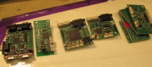
Different autopilot board revisions

This seemingly timely victory was, unfortunately, followed by many issues as we proceeded to switch from using electric propulsion, to an internal combustion engine. Due to our prior inexperience in small 2-stroke engines the noisy, dirty engine was the source of a great deal of frustration. Even when operating, its vibration would interfere with our inertial sensor, causing all sorts of dampening systems to be tried before a solution was obtained. This was also complicated by our small fuselage working area.

By the end however, the Autopilot seemed to be at a state where it could perform well in the competition. Unfortunately, due to the accumulation of issues that were still unresolved, we decided not to compete in 2009. In the next part of the 2009 summary, I will shed light on some of these problems and the plans for the 2010 competition.